Re: QL-VGA v2
Posted: Wed Jun 30, 2021 8:53 am
Hi,
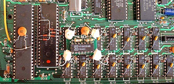
Is there an explanation of the modifications detailed in the picture.
Is there an explanation of the modifications detailed in the picture.
Hi,bwinkel67 wrote:That's what my board looks like...crazy US motherboards. I'm assuming this all had to do with FCC regulations?!?
Edit: Well, my RAM chips don't have those resistors across them...
The distorted sections of the screen (at least at their edges) shimmer between adjacent pixel values. It is very much like the pixels go in and out of sync a few times for every scan line.mk79 wrote:Is the picture static or does it change over time?
Some of the bodges are present. The ones on the RAM definitely are not.mk79 wrote:I'm still not sure what to make of it. QL-VGA v2 can handle pixel clocks from 9.976 to 10.024 MHz, so even if the crystal is way off it should cope. But then in your example picture we see that the lines are complete, which I think means that the correct clock is detected. It looks more like a frequency jitter within the line that I've never seen before this way. Does your QL also have the 74HC daughter board modification as seen in the picture here?
All the best, Marcel
The grainy picture is the only thing I have on it, US QLs are still somewhat under-described. But seeing that there is one 74 logic gate of some sorts with 2 resistors and the upper two wires being connected to the crystal I guess it's a standard "logic gate crystal oscillators" circuit. But as for why it is there, I don't have the foggiest idea.Derek_Stewart wrote:Is there an explanation of the modifications detailed in the picture.
Do you have a soldering iron and are you adventurous enough to disconnect the upper two wires from the QL board? Should be easy enough to re-attach after the fact. The lower wires are just for power as far as I can see and can stay. The upper wires are directly connected to the crystal, so it does mess with the clock in some way.varmfskii wrote:Sorry opening up the machine, there is definitely a daughter board in place.
Dave just bought a working US QL, maybe you can work with him to see if he can figure out what's going on.mk79 wrote:Without access to such a machine it's basically impossible for me to develop for it.
I am reasonably handy with a soldering iron. I'll try that. What does the 74HC mod do?mk79 wrote:Do you have a soldering iron and are you adventurous enough to disconnect the upper two wires from the QL board? Should be easy enough to re-attach after the fact. The lower wires are just for power as far as I can see and can stay. The upper wires are directly connected to the crystal, so it does mess with the clock in some way.
If not I can only offer you some refund deal of some sorts, I guess. Without access to such a machine it's basically impossible for me to develop for it.
Well, I've yet to meet somebody who knows, nobody has ever documented it. If it is what I think it is (again, I only know the one grainy photo) it's technically redundant, like Bwinkel my guess would be that it was due to some FCC thing. But fact is no QL outside of the US has this modification and they all work fine. And QL-VGA was tested with well over 50 very different QLs without any problems, so it would be interesting to see what disabling it will change. Thanks in advance for tryingvarmfskii wrote:I am reasonably handy with a soldering iron. I'll try that. What does the 74HC mod do?